close
Filter By
Company
Accuracy
Ambient Temperature
Connection Type
Flow Rate (l/min)
Medium Temperature
Nominal Diameter
Pressure Range
- 0...0.6 bar 1
- 0...0.6 bar__0...40 bar 5
- 0...0.6 bar__0...40 bar__PN 16/40 or Class 150/300 1
- 0...1.000 bar 1
- 0...1.000 mbar 1
- 0...1 bar__0...10 bar 1
- 0...1 bar__0...25 bar 1
- 0...1 bar__0...40 bar 1
- 0...10.000 bar 1
- 0...10 bar__0...600 bar 1
- 0...16 bar 1
- 0...25 bar 3
- 0...40 bar 1
- 0...60 bar 4
- 0...100 bar 1
- 0...250 bar 1
- 0...400 bar 2
- 0...600 bar 9
- 0...700 bar 3
- 0...1000 bar 2
- 0...1600 bar 1
- 2...20 bar 1
- 10 bar 1
- 10 bar__6 bar__8 bar 6
- 20 bar 1
- 25 bar__40 bar 2
- 25 mbar 1
- 40...400 mbar 1
- 100 bar 1
- 250 bar 1
- 300 bar 1
- 350...400 bar 2
- -0.2...21 bar 1
- -0.2...400 bar 1
- -0.95...40 bar 1
- -0.95...60 bar 1
- -1...1 bar__0...2.000 bar 1
- -1...1 bar__0...2500 bar 1
- -1...2 bar__0...1000 bar 1
- -1...3 bar__0...700 bar 1
- -1...3 bar__0...1000 bar 1
- -1...10 bar__0...1000 bar 1
- -1...18 bar 1
- -1...60 bar 1
- -1...210 bar 2
- -1...250 bar 1
- -1...400 bar 1
- -1...1000 bar 1
- Corresponding to flange specification 1
- From 400 mbar depending on diameter of diaphragm 1
- PN 10 10
- PN 10 €“ 100; Class 150 - 600 1
- PN 16 8
- PN 25 5
- PN 50 2
300 bar, 10 bar - 2...20 bar
3 items
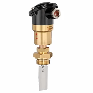
VH500 Paddle Flow Switch
1035
The SIKA VH500 paddle flow switch is modelled for applications such as cooling water monitoring, leak monitoring, and lubrication control. The SIKA VH 500 is placed with its paddle in flowing medium, which triggers the paddle. The resulting dynamic pressure causes the paddle to travel, which causes the actuation of integrated micro switches. SIKA flow switches monitor the flow of low-viscosity media in pipes. They offer a reliable solution for ensuring the minimum flow rate and thereby protecting high-quality systems and installations from damages. These flow switches work based on the well- established mechanical operating principles. Thanks to the different paddle lengths, the switch points of the paddle flow switches can be configured for a wide switching range.
- USD

CS Pressure Switch
5294
The Danfoss CS pressure switch series has a built-in pressure operated, three-pole switch. The contact position of which depends on the pressure in the connector and the range setting and adjustable differential. The Danfoss CS pressure switches are fitted with a manual switch that will lock the contact system in the open position independently of the pressure in the system. Pressure switches with relief valve are used in compressed air systems where pressure relief on the compressor piston before the start is required. The CS is suited for an automatic start and stop of air compressors and water boosters.
- USD

VTP 15 Turbine Flow Sensor
7821
The SIKA VTP 15 turbine flow sensor is made for flow measurement or dosing applications for liquids. Because of the very compact design, the extensive measuring range and the convincing precision of measurements, almost unlimited applications are possible. The sturdy bearing materials – sapphire and tungsten carbide – also guarantee an exceptionally long endurance. The liquid flowing into the SIKA VTP 15 turbine flow sensor is split into individual jets by the guiding blade. These jets hit the rotor evenly from different directions, setting the rotor in motion. The rotation speed of the rotor is then converted to an electrical pulse signal (frequency): The rotor is fitted with magnets and a Hall effect sensor detects the rotation of the rotor. A flow-proportional frequency signal (square-wave signal) is made available. The construction of the guiding blade and rotor enables to realize the very low start-up flow values.
- USD
1 - 3 of 3
1