close
Categories
Filter By
Company
Connection Type
Medium Temperature
Pressure Range
- 0...0.6 bar 1
- 0...0.6 bar__0...40 bar 5
- 0...0.6 bar__0...40 bar__PN 16/40 or Class 150/300 1
- 0...1.000 bar 1
- 0...1.000 mbar 1
- 0...1 bar__0...10 bar 1
- 0...1 bar__0...25 bar 1
- 0...1 bar__0...40 bar 1
- 0...10.000 bar 1
- 0...10 bar__0...600 bar 1
- 0...16 bar 1
- 0...25 bar 3
- 0...40 bar 1
- 0...60 bar 4
- 0...100 bar 1
- 0...250 bar 1
- 0...400 bar 2
- 0...600 bar 9
- 0...700 bar 3
- 0...1000 bar 2
- 0...1600 bar 1
- 2...20 bar 1
- 10 bar 1
- 10 bar__6 bar__8 bar 6
- 20 bar 1
- 25 bar__40 bar 2
- 25 mbar 1
- 40...400 mbar 1
- 100 bar 1
- 250 bar 1
- 300 bar 1
- 350...400 bar 2
- -0.2...21 bar 1
- -0.2...400 bar 1
- -0.95...40 bar 1
- -0.95...60 bar 1
- -1...1 bar__0...2.000 bar 1
- -1...1 bar__0...2500 bar 1
- -1...2 bar__0...1000 bar 1
- -1...3 bar__0...700 bar 1
- -1...3 bar__0...1000 bar 1
- -1...10 bar__0...1000 bar 1
- -1...18 bar 1
- -1...60 bar 1
- -1...210 bar 2
- -1...250 bar 1
- -1...400 bar 1
- -1...1000 bar 1
- Corresponding to flange specification 1
- From 400 mbar depending on diameter of diaphragm 1
- PN 10 10
- PN 10 €“ 100; Class 150 - 600 1
- PN 16 8
- PN 25 5
- PN 50 2
-1...3 bar__0...700 bar, PN 25 - -0.95...40 bar
7 items

P 40.2 Pneumatic Hand Test Pump
4868
The SIKA P 40.2 pneumatic hand test pump is designed to enable the direct connection of all pressure systems to be tested using adapters. The test sample is easily connected using the rugged industrial hose with integrated quick coupling and supplied adapters. The reference is fitted directly at the top of the pump using a positioning adapter. The required test pressure is initially generated using the handles and then adjusted precisely with the fine adjustment valve. As a result, the pressure on both instruments is the same. The pressure relief valve allows continuous pressure reduction and ensures accurate and easy testing, even with decreasing pressure. Air is used as pressure media. Especially in application areas in which wetting of the test sample is not allowed, or the use of aggressive or ionising substances must be avoided, air is the ideal test medium. SIKA˜s pneumatic test pump type P40.2 fulfils requirements that in many cases can only be covered by several pumps from other suppliers. In the simplest case, the pressure is indicated by an analogue pressure gauge. An easy to read digital pressure gauge or hand-held instrument can also be used. The accuracy or adjustment of the pressure measuring device being tested can be checked by comparing the indicated reference value with the measured value for the device under test. OEM version and full version Depending on the model a matching pressure hose is part of the basic configuration of the OEM version of the test pump. The hydraulic hoses are fitted with a self-sealing quick coupling. Inch, conical or metric adapters for all commonly used connection threads are available in the full version. A matching seal kit is also included with the pump. All of the equipment is held in a carrying case with a foam-rubber insert.
- USD
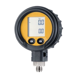
D-Ex Digital Pressure Gauge
4877
The SIKA D-Ex digital pressure gauge is suitable for both stationary and mobile measurement and display of pressure. The SIKA D-Ex digital pressure gauge can be used as a reference to explain the checking, adjustment and calibration of other pressure measurement devices directly on-site. High accuracy in the signal acquisition is achieved by using high-performance measuring cells with electronic linearisation of the characteristic curve. Suitable instruments are available for a wide variety of measurement tasks. Ease of use is assured by innovative design and advanced technology. All essential functions for everyday use can be selected conveniently at the press of a button. Excellent protection against dust and moisture is provided by a membrane keypad or rubber buttons. Integrated supplementary functions make our digital pressure gauges true all-rounders. Tare / Zero-Function User-defined zero point setting at the push of a button makes offset adjustment easy and eliminates the need for tedious mechanical adjustment. Single-point adjustment allows the linear characteristic curve to be shifted in positive or negative direction over the entire measuring range. Selectable pressure units Another feature is the large selection of pressure units. Up to 6 different units are possible “ far more than any complicated dual-scale or multi-scale gauge can offer. The required display unit is selected directly on the digital pressure gauge and is indicated on display. No conversion necessary; the desired value can be read directly. Min / Max Displays and Peak function Experience shows that excess pressure and pressure peaks significantly higher than normal operating pressure occur at some measuring points. Min / max displays and fast peak value measurement cycles in digital pressure gauges assist in system analysis and allow peak values to be determined. This allows incorrect readings and violations of range limits to be detected and helps avoid damage to pressure systems. Preventive service is often less expensive than repairing or replacing defective instruments.
- USD

VHS Flow Switch
7589
The SIKA VHS flow switches are used for monitoring volume flows. Depending on conditions, the SIKA VHS flow switch is available for various nominal widths and set-point ranges. The SIKA VHS flow switch contains a paddle system to whose end a permanent magnet is attached. Above this magnet is a reed contact, located outside the flow of fluid. A second magnet creates the force necessary to reset the switch back to the no-flow position. When the flow being monitored pushes against the paddle system, the paddle swings away. This changes the position of the magnet in relation to the reed contact and thus activates the connection. As soon as the flow is interrupted, the paddle moves back to its starting position, thus activating the reed contact once again. The force necessary to push the magnet back is provided by the two magnets repelling each other. Using magnetic force instead of the usual leaf spring means that the switch is considerably more stable in the long term and much less sensitive to pressure peaks.
- USD

VHS09 Flow Switch
7600
The SIKA VHS09 flow switches are used for monitoring volume flows. Depending on conditions, the SIKA VHS09 flow switch is available for various nominal widths and set-point ranges. The SIKA VHS09 flow switch contains a paddle system to whose end a permanent magnet is attached. Above this magnet is a reed contact, located outside the flow of fluid. A second magnet creates the force necessary to reset the switch back to the no-flow position. When the flow being monitored pushes against the paddle system, the paddle swings away. This changes the position of the magnet in relation to the reed contact and thus activates the connection. As soon as the flow is interrupted, the paddle moves back to its starting position, thus activating the reed contact once again. The force necessary to push the magnet back is provided by the two magnets repelling each other. Using magnetic force instead of the usual leaf spring means that the switch is considerably more stable in the long term and much less sensitive to pressure peaks.
- USD

VHS06 Flow Switch
7604
The SIKA VHS06 flow switches are used for monitoring volume flows. Depending on conditions, the SIKA VHS06 flow switch is available for various nominal widths and set-point ranges. The SIKA VHS06 flow switch contains a paddle system to whose end a permanent magnet is attached. Above this magnet is a reed contact, located outside the flow of fluid. A second magnet creates the force necessary to reset the switch back to the no-flow position. When the flow being monitored pushes against the paddle system, the paddle swings away. This changes the position of the magnet in relation to the reed contact and thus activates the connection. As soon as the flow is interrupted, the paddle moves back to its starting position, thus activating the reed contact once again. The force necessary to push the magnet back is provided by the two magnets repelling each other. Using magnetic force instead of the usual leaf spring means that the switch is considerably more stable in the long term and much less sensitive to pressure peaks.
- USD

VH0 Micro Flow Switch
7606
The SIKA VH0 flow switches are used for monitoring volume flows. Depending on conditions, the SIKA VH0 flow switch is available for various nominal widths and set-point ranges. The SIKA VH0 flow switch contains a paddle system to whose end a permanent magnet is attached. Above this magnet is a reed contact, located outside the flow of fluid. A second magnet creates the force necessary to reset the switch back to the no-flow position. When the flow being monitored pushes against the paddle system, the paddle swings away. This changes the position of the magnet in relation to the reed contact and thus activates the connection. As soon as the flow is interrupted, the paddle moves back to its starting position, thus activating the reed contact once again. The force necessary to push the magnet back is provided by the two magnets repelling each other. Using magnetic force instead of the usual leaf spring means that the switch is considerably more stable in the long term and much less sensitive to pressure peaks. Microswitch A microswitch used as a switching element allows a higher electrical switching capacity than a reed switch. The resetting force required by the paddle system is produced by a leaf spring.
- USD

VH3 Flow Switch
7610
The SIKA VH3 flow switches are used for monitoring volume flows. Depending on conditions, the SIKA VH3 flow switch is available for various nominal widths and set-point ranges. The SIKA VH3 flow switch contains a paddle system to whose end a permanent magnet is attached. Above this magnet is a reed contact, located outside the flow of fluid. A second magnet creates the force necessary to reset the switch back to the no-flow position. When the flow being monitored pushes against the paddle system, the paddle swings away. This changes the position of the magnet in relation to the reed contact and thus activates the connection. As soon as the flow is interrupted, the paddle moves back to its starting position, thus activating the reed contact once again. The force necessary to push the magnet back is provided by the two magnets repelling each other. Using magnetic force instead of the usual leaf spring means that the switch is considerably more stable in the long term and much less sensitive to pressure peaks.
- USD
1 - 7 of 7
1